Geometric Modeling
Geometric modeling is the part of computer graphics that invents ways to describe shape inside a computer so that the shape can be drawn, analyzed, manufactured, or simulated.
10 frameworks, from 1960 to today · Computer Graphics · Computer Science
- Bézier and Coons Patch Modeling 1960-1985
- Non-uniform rational B-spline 1972-Present
- Solid Modeling 1972-Present
- Boundary Representation 1975-Present
- Constructive Solid Geometry 1975-Present
- Subdivision surface 1978-Present
- Implicit Surfaces and Distance Fields 1982-Present
- Parametric and Variational Design 1985-Present
- Geometry Processing 1995-Present
- Neural Shape Representation 2018-Present
Overview
Geometric modeling is the part of computer graphics that invents ways to describe shape inside a computer so that the shape can be drawn, analyzed, manufactured, or simulated12. Its central problem is representation: a physical object—a car body, a teapot, a bone, a gearbox—has to be turned into numbers and equations that a machine can store and manipulate, and different representations make different things easy. A representation that makes it easy to draw a smooth fender may make it hard to compute whether a drill will pierce the metal; a representation that makes it easy to test solidity may make it awkward to sculpt a free-form curve. Much of the field's history is the story of building representations that trade these conveniences off, and then of building bridges between them. What is at stake is not just pictures but the objects themselves: the same models feed animation, engineering analysis, 3D printing, and medical planning, so a modeling choice made in a design studio can propagate all the way to a factory floor.
Curves and patches for car bodies and aircraft
The earliest practical need came from manufacturing. In the 1950s and 1960s, aircraft and automobile companies wanted to describe smooth free-form surfaces—surfaces with no simple algebraic formula, shaped by aesthetic and aerodynamic judgment—in a form a computer could store and a milling machine could cut. The French engineer Pierre Bézier, working at Renault, developed the curve representation now called the Bézier curve, in which a curve is defined by a small set of control points that pull it into shape; the curve passes through the first and last points and is drawn toward the others without necessarily touching them. Bézier published his work in the 1960s, and the same idea was developed independently around the same period by Paul de Casteljau at Citroën, whose algorithm for evaluating such curves was kept as a company secret for years. The appeal was direct manipulation: a designer could move a control point and watch the curve respond predictably, which matched the way stylists already worked with physical splines.
The other foundational idea came from Steven Coons at MIT, who in the 1960s described how to build a curved surface patch from its four boundary curves—a Coons patch. This let designers stitch patches together along shared edges, so a complex surface could be assembled from manageable pieces. Bézier patches and Coons patches together established the patchwork approach: model a surface as a quilt of smooth pieces. The problem this left was continuity—how to make neighboring patches meet without a visible crease—and that question drove the next generation of work.
B-splines, NURBS, and the standardization of free-form shape
Bézier curves have a limitation: moving one control point changes the whole curve, and joining many curves smoothly takes care. The B-spline, developed in the mid-twentieth century and brought into computer-aided design in the 1970s, solved this by making each control point influence only a local stretch of the curve, and by building smoothness into the representation itself. A B-spline curve is defined by control points and a knot vector—a list of parameter values that says where each piece of the curve begins and ends—and the mathematics guarantees a chosen degree of continuity across the joins. This made it practical to model long, complicated curves and surfaces as single objects rather than hand-stitched patches.
The generalization that came to dominate industry is the NURBS curve and surface: a Non-Uniform Rational B-Spline, which adds weights to the control points so that the representation can describe exact circles, ellipses, and other conic sections—shapes that ordinary polynomial splines can only approximate. NURBS were formalized and popularized in the 1970s and 1980s, with Kenneth Versprille's doctoral work on rational B-splines among the key steps, and they became the standard exchange format for free-form geometry in CAD. The reason is telling: a single representation could hold both the free-form styling surfaces and the precise engineering features (a cylindrical hole, a conical chamfer) that a mechanical part needs. The IGES and later STEP data-exchange standards carried NURBS geometry between incompatible software systems, and NURBS remain the backbone of most commercial CAD today.
Solid modeling: from surfaces to objects with insides
A surface model describes a skin. It cannot answer whether a point is inside the object, and that question is essential for manufacturing: you cannot reliably compute a volume, a mass, or a machining path from a skin alone. Solid modeling, developed mainly from the 1970s onward, set out to represent objects as closed, unambiguous solids. Two rival approaches emerged, and their competition shaped the field.
Constructive solid geometry (CSG) builds objects by combining simple primitives—blocks, cylinders, spheres—with Boolean operations: union, intersection, and difference3. A part is stored as a tree of operations, so a hole is literally "this block minus this cylinder." CSG is compact and robust in principle, because the primitives are exact, but extracting a surface mesh from a CSG tree for display or analysis requires evaluating the tree, which can be expensive and delicate at the seams.
Boundary representation (B-rep) instead stores the solid by its boundary: faces, the edges where faces meet, and the vertices where edges meet, with enough topological information to know which side is inside4. B-rep gives direct access to the surface geometry, which suits display and machining, but maintaining a consistent, watertight boundary through complex operations is hard—small numerical errors can leave a face unclosed or an edge shared by the wrong number of faces. The two representations coexisted and still do: many systems keep a CSG history alongside a B-rep result, and the long-running research problem of "non-manifold" modeling—representing shapes where more than two faces meet at an edge, or where a surface touches itself—grew out of the practical failures of both.
Parametric and variational design
As CAD spread through industry in the 1980s and 1990s, a further shift changed how designers worked. Instead of fixing geometry directly, parametric design lets a model be defined by dimensions and constraints—this hole is 10 mm from that edge, this face is parallel to that one—and the system solves for geometry that satisfies them. Variational design goes further, treating the constraints as an equation system to be solved when any dimension changes, so that editing one number ripples correctly through the whole model. This made models reusable as families of parts and made design intent explicit. The approach is closely associated with the rise of feature-based and history-based CAD in the late 1980s and 1990s, and it is now the default working style in mechanical design software. Its weakness is fragility: a constraint system can become over- or under-constrained, and a change that seems small can make the solver fail or produce a surprising shape.
Subdivision surfaces: smoothness from coarse control meshes
By the 1990s, animation studios faced a different problem. Character models needed to be smooth, but animators wanted to control them with relatively few, easily edited polygons. Subdivision surfaces answered this: start with a coarse polygon mesh and repeatedly refine it by a fixed rule, each step inserting new vertices and averaging positions so the mesh converges to a smooth limit surface. The Catmull–Clark scheme, published by Edwin Catmull and Jim Clark in 1978, generalizes B-spline surfaces to arbitrary meshes and produces smooth surfaces from quad-based control cages; the Loop scheme, published by Charles Loop in 1987, does the same for triangle meshes56. The practical breakthrough was that a modeler could work with a simple cage and get a smooth surface automatically, with the cage's shape controlling the result. Subdivision surfaces became standard in film production—Pixar's use of them in feature animation in the 1990s and 2000s is well documented—and they now sit alongside NURBS in CAD as well, since subdivision can represent shapes that are awkward for patch-based splines.
Implicit surfaces and distance fields
A parallel tradition describes shape not by a boundary but by a function: an implicit surface is the set of points where some function equals zero, with the sign of the function telling inside from outside. A distance field stores, for each point in space, the distance to the nearest surface, which makes it easy to blend shapes, offset them, and test proximity. These representations are compact for organic and blobby forms and are natural for simulation and collision. They became practical for graphics as volumetric grids and, later, sparse and adaptive data structures made them affordable, and they underpin techniques for modeling liquids, soft bodies, and scanned objects. Their weakness is resolution: a grid-based field must be fine enough to capture detail, and extracting a surface mesh from it (the marching cubes algorithm, published by Lorensen and Cline in 1987, is the classic method) produces many small triangles.
Geometry processing: making meshes usable
As scanned and modeled meshes became common in the 1990s and 2000s, a new set of problems appeared: real meshes are noisy, have irregular connectivity, and are often too dense or too sparse for a given task. Geometry processing grew as the discipline of cleaning, simplifying, smoothing, parameterizing, and analyzing meshes7. Mesh simplification reduces triangle count while preserving shape; remeshing rebuilds connectivity for better quality; parameterization flattens a curved surface onto a plane so textures can be painted; and spectral methods analyze a mesh's vibration-like modes to find features. This work turned the mesh from a mere display format into an object of study in its own right, and it connects modeling to rendering, simulation, and 3D printing.
Neural shape representation
The most recent turn borrows from machine learning. Neural shape representations encode a shape in the weights of a neural network—for example, a network that, given a 3D point, predicts whether it is inside the object or how far it is from the surface8. Such representations can be trained from examples, can interpolate between shapes, and can be queried at any resolution. They are young and still being evaluated against the classical representations, but they inherit the field's oldest question: what is the right way to describe shape so that a machine can store it, edit it, and reason about it? The answer today is plural—NURBS and B-rep in engineering, subdivision and polygon meshes in animation, implicit fields in simulation and scanning, and neural fields in research—and the open problems are the old ones in new dress: robustness of Boolean operations, guaranteed watertightness, smooth continuity across representations, and the conversion between them without loss.
References
- Geometric modeling, Wikipedia
- Computational geometry, Wikipedia
- Constructive solid geometry, Wikipedia
- Boundary representation, Wikipedia
- Loop subdivision surface, Wikipedia
- Catmull–Clark subdivision surface, Wikipedia
- Geometry processing, Wikipedia
- Neural field, Wikipedia
The frameworks of Geometric Modeling
Each framework is a way of working the field has used: when it held, and the question it answers.
- 1960-1985
Bézier and Coons Patch Modeling
How can a few control points define a smooth free-form curve or patch?
- 1972-Present
Non-uniform rational B-spline
How can splines give local control and exact conics?
- 1972-Present
- 1975-Present
Boundary Representation
How can a solid be stored by its bounding faces and edges?
- 1975-Present
Constructive Solid Geometry
How can solids be built by combining primitives with Boolean operations?
- 1978-Present
Subdivision surface
How can repeated refinement of a coarse mesh yield a smooth surface?
- 1982-Present
Implicit Surfaces and Distance Fields
How can a function's zero set and sign describe a shape?
- 1985-Present
Parametric and Variational Design
How can dimensions and constraints drive geometry automatically?
- 1995-Present
Geometry Processing
What algorithms operate on and improve digital shape meshes?
- 2018-Present
Neural Shape Representation
How can neural networks learn to represent and generate shape?
How the ideas connect
Each arrow runs from an earlier idea to the later one it shaped. The list below says what passed between them.
Non-uniform rational B-spline grew out of Bézier and Coons Patch Modeling
B-spline curves and surfaces generalized the Bézier representation: Bézier curves are a special case of B-splines, and the knot-vector machinery was developed to give local control where Bézier control points had global influence. The NURBS formulation added weights to B-splines to represent conics exactly, extending the patch-modeling program of F1.
Carried by Kenneth Versprille; Pierre Bézier.
Subdivision surface grew out of Non-uniform rational B-spline
The Catmull–Clark subdivision scheme was explicitly designed as a generalization of B-spline surfaces to arbitrary meshes, reproducing bicubic B-spline surfaces on regular quad grids while allowing extraordinary vertices. Subdivision thus extended the spline representation from rectangular patch topology to any control mesh.
Carried by Edwin Catmull; Jim Clark.
Solid Modeling influenced by Bézier and Coons Patch Modeling
Early solid modeling work confronted the gap left by surface patch models: a quilt of Bézier or Coons patches describes a skin but not a closed solid, and the need to guarantee watertight, manufacturable objects motivated representing solids explicitly. The patchwork approach supplied the surface geometry that solid modelers had to enclose.
Parametric and Variational Design influenced by Solid Modeling
Parametric and variational design built on solid modeling's explicit representation of engineering features: constraints and dimensions were attached to the faces and features of a solid so that editing a dimension could regenerate the geometry. The feature-based, history-based CAD systems of the late 1980s grew out of solid modelers.
Geometry Processing influenced by Solid Modeling
Geometry processing took solid models and boundary representations as its input objects, developing algorithms for smoothing, simplification, parameterization and repair of meshes extracted from CAD representations. The robustness problems of B-rep and CSG evaluation helped motivate the mesh-centered processing agenda.
Constructive Solid Geometry rival of Boundary Representation
B-rep and CSG competed through the 1970s and 1980s as the working representation of solids: CSG is compact and exact at the primitive level but needs tree evaluation for a surface, while B-rep gives direct surface access but is fragile under Boolean operations. Many systems ended up keeping a CSG history alongside a B-rep result.
Parametric and Variational Design influenced by Boundary Representation
Constraint solvers in parametric CAD operated on the faces, edges and vertices of a boundary representation, solving for positions that satisfy dimensional and geometric constraints. B-rep topology supplied the entities over which variational systems posed their equations.
Geometry Processing influenced by Subdivision surface
Subdivision surfaces gave geometry processing a family of multiresolution mesh representations, and algorithms for editing, compressing and analyzing meshes were built on subdivision hierarchies. The coarse-cage-to-smooth-limit idea carried into mesh processing pipelines.
Neural Shape Representation influenced by Implicit Surfaces and Distance Fields
Neural implicit representations, which output a signed distance or occupancy value from a coordinate, are direct descendants of implicit surface and distance field representations, with a neural network replacing the stored grid or function. The inside/outside sign convention and distance-field formulation carried over intact.
Neural Shape Representation influenced by Geometry Processing
Neural shape representations took the tasks and benchmarks of geometry processing—reconstruction from point clouds, shape completion, mesh generation—and replaced hand-designed representations with learned ones. The datasets and evaluation practices of mesh processing carried directly into neural shape work.
Subdivision surface influenced by Bézier and Coons Patch Modeling
Subdivision surfaces kept the patch-modeling idea of a coarse control structure that determines a smooth limit shape, but replaced stitched polynomial patches with a recursive refinement rule. The continuity problem that drove work after Bézier and Coons patches is what subdivision solved by construction.
Parametric and Variational Design influenced by Non-uniform rational B-spline
Parametric CAD carried over the spline idea that geometry is generated from a small set of defining data rather than stored point by point; dimensions and constraints took the place of control points as the parameters. NURBS remained the underlying geometry that constraint solvers manipulated.
Neural Shape Representation influenced by Subdivision surface
Neural shape methods adopted the coarse-control-mesh idea, learning or predicting a low-resolution cage or latent code from which a smooth surface is generated. Subdivision-style refinement from coarse to fine appears in neural mesh generation pipelines.
Geometry Processing influenced by Implicit Surfaces and Distance Fields
Implicit surfaces and distance fields supplied geometry processing with tools for reconstruction, remeshing and collision, since sign and distance queries are easy on volumetric representations. Processing pipelines often convert between mesh and implicit forms.
Beyond the field
Where Geometric Modeling's ideas came from in other fields, and what they led to there: the strongest 12 of 27 links.
Bézier and Coons Patch Modeling influenced Spline and subdivision surface modeling in Computer Graphics
Bézier and Coons patch modeling supplied the polynomial curve and patch formulations that spline modeling generalized; de Casteljau and Bézier curves were reworked into B-spline and later subdivision schemes by researchers such as Riesenfeld and Catmull-Clark.
Carried by Pierre Bézier; Steven Coons; William Gordon.
Parametric and Variational Design influenced Parametric architecture in Architectural Theory
Parametric and variational design in geometric modelling, with its constraint solvers and history-based feature modelling, was taken over directly by architectural parametric systems.
Parametric and Variational Design influenced Parametric design in Digital Design Theory
Parametric and variational design in geometric modeling provided the constraint-solving and feature-based parametric methods that parametric design tools in architecture and design built upon.
Parametric and Variational Design influenced Parametric design in Architecture
Parametric and variational modelling from geometric modelling research supplied the constraint-based techniques that architectural parametric design adopted.
Bézier and Coons Patch Modeling influenced by Classical differential geometry of curves and surfaces in Differential Geometry
The patch formulations of Bézier and Coons rest on the classical differential geometry of curves and surfaces: parametric surface representation, tangent and normal continuity between patches, and curvature conditions all come from that tradition. Coons and Bézier drew on these concepts when designing their surface schemes for aircraft and automobile design in the early 1960s.
Carried by Steven Anson Coons; Pierre Bézier.
Bézier and Coons Patch Modeling influenced Polygon mesh in Computer Graphics
Bézier and Coons patch modeling provided the parametric surface representations that polygon mesh techniques approximated and tessellated for rendering.
Bézier and Coons Patch Modeling influenced Texture and appearance mapping in Computer Graphics
Texture mapping was first demonstrated on bicubic patch models: Ed Catmull's 1974 thesis mapped images onto surfaces defined by Bézier and Coons patches, using the patches' parametric coordinates as texture coordinates. The patch formulation supplied the parameterisation that made texture mapping practical.
Carried by Edwin Catmull.
Non-uniform rational B-spline influenced by Differential geometry of curves and surfaces in Geometry
NURBS curves and surfaces are parametric differential-geometric objects: their tangent, normal and curvature properties and their continuity conditions come from the classical differential geometry of curves and surfaces. The NURBS literature routinely invokes these classical results.
Boundary Representation influenced by Polygon mesh in Computer Graphics
Boundary representation stores a solid as a closed polyhedral or curved-face mesh with vertices, edges and faces, so polygon-mesh data structures are the direct substrate of B-rep. The half-edge and winged-edge structures of B-rep are refinements of mesh connectivity representations.
Carried by Ian Braid; Bruce Baumgart.
Boundary Representation influenced by Spline and subdivision surface modeling in Computer Graphics
B-rep faces are typically bounded by spline and subdivision surface patches, so the surface-modeling machinery of splines was incorporated into boundary representations. The two modeling traditions were combined in CAD systems from the mid-1970s.
Subdivision surface influenced by Polygon mesh in Computer Graphics
Subdivision surfaces operate on polygon meshes, refining a control mesh by repeated subdivision. The mesh data structures and refinement schemes of polygon mesh modeling are the direct basis of subdivision surface algorithms.
Carried by Edwin Catmull; James Clark.
Implicit Surfaces and Distance Fields influenced Deformable Models in Medical Image Analysis
Implicit surfaces and level-set distance fields provided the numerical machinery for geometric deformable models, letting contours evolve as level sets of a higher-dimensional function. This passed into medical image segmentation in the mid-1990s.
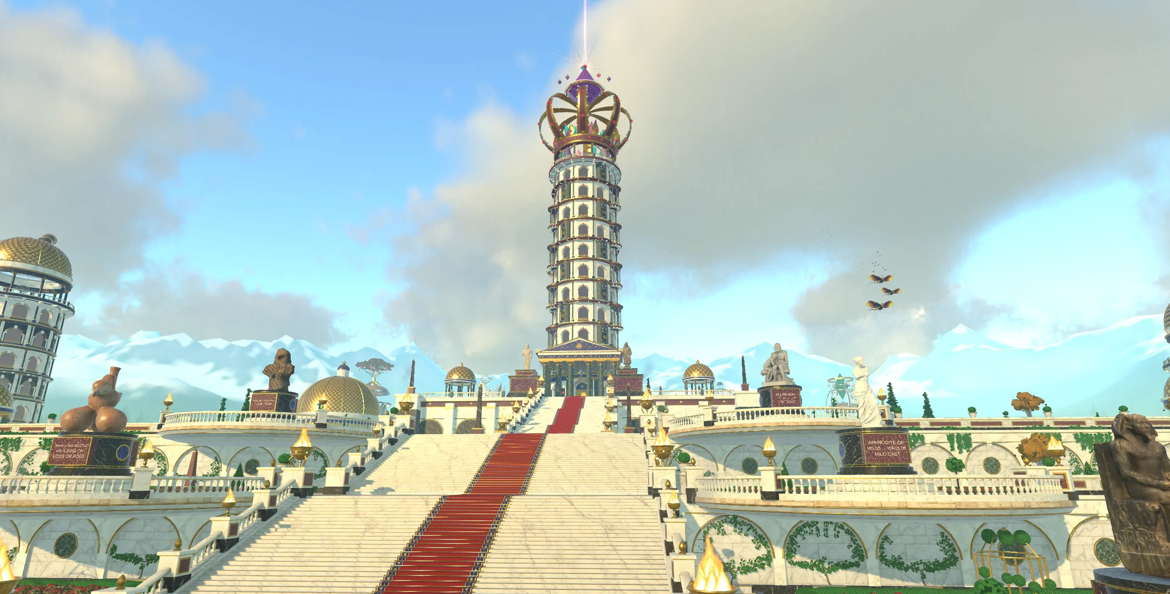
Geometric Modeling is a planet in Nousfarer
Its city has a tower for each of these 10 frameworks. Land, walk in, and climb one concept at a time.
Land on Geometric ModelingRelated fields
Fields its ideas are linked to
- Computer Graphics 8 links
- Differential Geometry 3 links
- Geometry 2 links
- Medical Image Analysis 2 links
- Calculus Of Variations 1 link
- Architectural Theory 1 link
- Architecture 1 link
- Digital Design Theory 1 link
- Modern Architecture 1 link
- Computational Imaging 1 link
- Graphics Rendering 1 link
- Algebraic Geometry 1 link
More in Computer Graphics
- Computational Imaging
- Computer Animation
- Computer Graphics
- Game Technology
- Graphics Rendering
- Physical Simulation
- Virtual Reality
See where Geometric Modeling sits on the Map of Human Knowledge